


Contact Us
Email: up@up1.co.uk
United Publications
85 Croydon Road,
Keston,
Kent,
BR2 8HU,
United Kingdom.
Phone: 07790 247934
Intl: +44 7790 247934
Copyright © 2000-2025 United Publications is part of United Publications Distribution Ltd., All rights reserved.
Announcements
Ramp_Install
Switch power off.
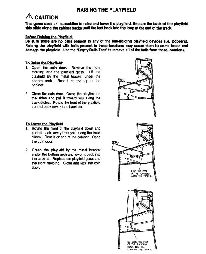
To install you will need to raise playfiled into 90 degree angle used for maintenance (See section 1-8 operations manual or below image).
Locate skip ramp assembly.
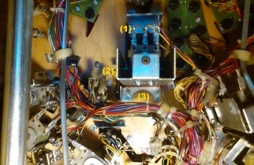
(1) Disconnect solenoid power orange, yellow & red wires by slowing pulling on metal crimp terminal (NOT WIRE).
(2) Disconnect 2 pin connector for microswitch with green & white wires on left side.
Before removing 4 screws put something under screws to catch them and/or use magnetic screwdriver. Dropping these screws into machine is annoying.
(3) Carefully remove 4 screws. Remember to hold skip ramp assembly before removing last screw.
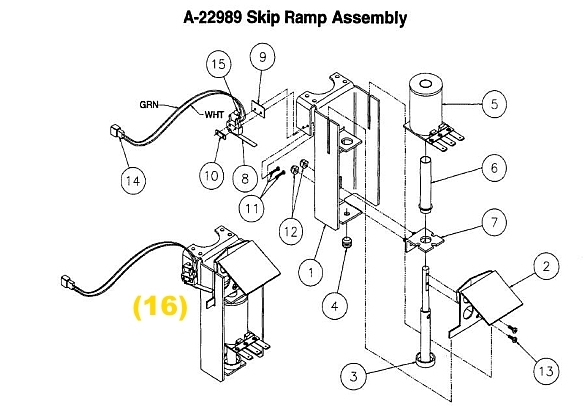
Remove old ramp bracket by removing 2 screws (13). See section 2-17 operations manual or below image.
This will allow to remove ramp bracket without disassembling whole ramp assembly.
(Optional extra suggested ramp improvement. If you do not have spring on solenoid suggest adding one at this point
see "Up/Down Ramp Improvement" on this web site for more information: https://www.aaarpinball.com/RFM/RFM.htm)
Fit new ramp bracket making sure that ramp bracket is flush with armature/pole (3). Use lock washer enclosed on both screws.
Make sure arm of ramp bracket is under mircoswitch arm (16)
Screw back completed skip ramp assembly. Reconnect solenoid power orange (Left), yellow (Middle) & red (Right).
Reconnect 2 pin connector for microswitch with green & white wires on left side.
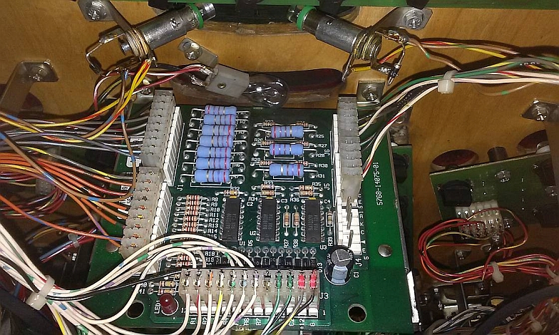
Connect power cable to 10-0pto Switch Board located above skip ramp assembly into J4 (Normally not used).
Missing pin on connector & board shows which way around connect should be fitted.
(Note if you have something already connected to J4, cable provided has pass through connector)
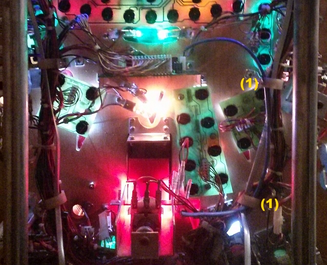
Put lose cable into cable holders fitted to playfield (1).
Installation complete.
NOTE:
RGB LED version of ramp has 4 terminals.
Shipped set to RED Brown/Black wire & Orange/Red connected.
To set differ colours see list below (Brown/Black wire always connected):
Orange/Red only connected = Red
Green only connected = Green
Blue only connected = Blue
Orange/Red & Green connected = Yellow
Orange/Red & Blue connected = Purple
Green & Blue connected = Cyan
All wires connected = White